Společnost HW group s.r.o. je výrobcem RME (Remote Monitoring Ecosystem). Naše produkty se používají pro vzdálený monitoring datových center, mrazáků s vakcínami, technologických místností a podobně. Používá se také pro měření spotřeby energie.
RME (Remote Monitoring Ecosystem) je hlavním zaměřením společnosti HW group. Naše společnost se dynamicky rozrůstá a námi vyvinutý systém RME je spolehlivý a osvědčil se již v mnoha projektech. Máme široký záběr od zákazníků se 2-3 zařízeními s několika senzory, až po instalace s několika stovkami zařízení a tisíci senzorů v jednom projektu.
Společnost HW group sídlí v Praze v České republice. Naše portfolio nyní tvoří více než 300 různých produktů a distribuujeme je po celém světě se sítí 50 distributorů. Naše distribuční síť v současné době pokrývá Evropu, Střední východ, Jižní a Severní Ameriku.


Standalone Monitoring produkty mohou fungovat s portálem nebo zcela samostatně. Zařízení přímo odesílají emaily, lze je připojit přes SNMP do NMS (Network Monitoring Systém). Produkty jsou víceúčelové, jejich konfigurace je složitější a připojení do portálu (HWg-cloud nebo SensDesk) je jen jedna z funkcí. Připojení zařízení do portálu nijak neomezuje odesílání alarmů ze zařízení a ostatní standalone funkce.
Řada jednodušších IT zařízení nabízí pouze sériové rozhraní pro lokální obsluhu a sběr dat. S převodníky IP serial lze snadno realizovat dálková sběr dat i řízení systémů prostřednictvím sítí Ethernet, v podobě místních LAN i rozsáhlých WAN sítí. Data tak lze předávat prakticky kamkoli a zařízení je možné dohledovat centrálně, bez ohledu na jejich fyzické umístění.

Řízení přístupu do budov je nedílnou součástí řízení moderních budov i zajištění bezpečnosti osob. Přístupové systémy nabízejí řadu řešení pro různé typy kancelářských i průmyslových budov, veřejných institucí i škol. Zároveň poskytují nástroje pro evidenci docházky a osob uvnitř prostoru a autorizaci přístupu do vybraných prostor a zón.
Hledám řešení
Nástroj pro výběr senzorů poskytuje rychlý přehled zařízení, dostupných pro měření různých technických a fyzikálních veličin. Vyberte si typ měření, zobrazí se dostupná zařízení.
- Senzory
- Řešení
- Zařízení
Příklady řešení

Monitoring teploty ve zdravotnictví
Dohled teploty v lednicích a skladech, které jsou určeny k uchovávání léků a potřeb se stanovenou teplotou.
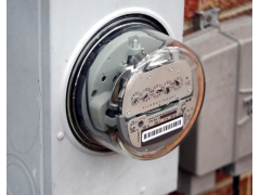
Spotřeba energie v bytových domech
Optimalizace spotřeby elektrické energie s využitím zařízení HWg-PWR.
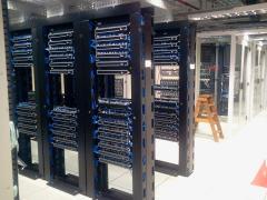
Monitoring prostředí a přístupové systémy v datacentrech
Ucelené řešení monitoringu prostředí a řízení přístupu pro datová centra.